
Control Card
The control card is in charge of all the calculations needed to drive the IGBTs. The MCU in the center comes with TI InstaSpin to facilitate in these calculations. Additionally, the control card has hardware to determine whether an overcurrent or overvoltage situation is happening according to the signals it receives from the Parent Board. In the instance of a fault, the control card sends a reset signal to the Gate Driver Board to prevent any damage to the motor.
Additionally, the board contains a sturdy CAN transceiver and common mode choke from which it can be programmed with via interface with the parent board, or alternatively through JTAG. Every utilized pin for the MCU has a resistor and capacitor pair to aid in blocking noise.
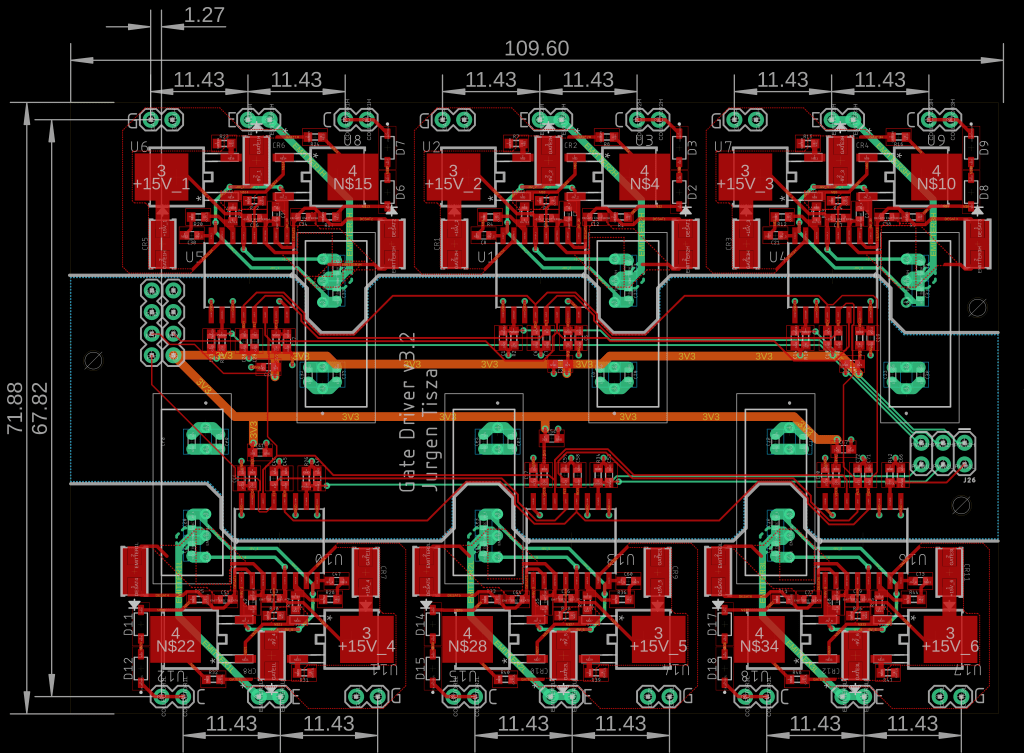
Gate Driver Circuit
A circuit designed to drive 6 separate IGBTs as quickly as possible. Utilizes a totem pole BJT current amplifier along with a Miller Clamp to charge and discharge the gate of IGBTs faster. The design has desaturation detection, is able to send ready and fault signals, as well as receive reset signals to preserve the AC Motor in events of short circuiting via soft turn off. Additionally, the board is clearly and cleanly isolated with a thick line between HV and LV to abide by competition regulations
This board is connected to the parent board, and receives PWM signals from the control card.
